Dana 25/27 Front Axle Tech and Troubleshooting - CJ-5
Bendix Universal Joint
• Place the differential half of the axle shaft in a vise, with the ground portion above the jaws.
• Install the center ball (one with hole drilled in it) in the socket in the shaft, with the hole and groove facing you.
• Drop the center ball pin into the drilled passage in the wheel half of the shaft.
• Place the wheel half of the shaft on the center ball. Then slip three balls into the raceways.
• Turn the center ball until the groove lines up with the raceway for the remaining ball. See Fig. 222. Slip the ball into the raceway and straighten up the wheel end of the shaft.
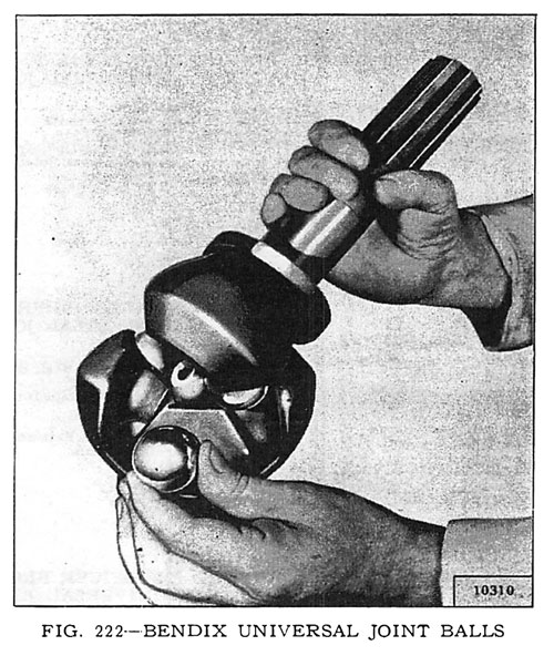
• Turn the center ball until the center ball pin drops into the hole drilled in the ball.
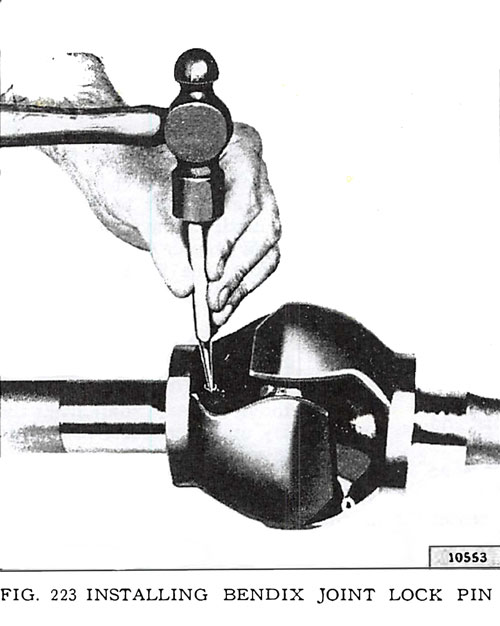
• Install the retainer pin (lock pin) and prick punch both ends to securely lock it in place. Always use a new retainer pin if available. See Fig. 223. (M-7, p 189)
Rzeppa Universal Joint
After the assembly has been removed, the universal joint may be disassembled as follows:
• Inspect to determine the method of attachment of the front axle shaft to the joint. Where three screws are used, follow step b. Where there are no screws, follow step c. After the axle shaft has been separated from the joint, follow steps d through h for both types.
• Remove the three screws holding the front axle shaft to the joint. Pull the shaft free of the splined inner race. To remove the axle shaft retainer, remove the retainer ring on the axle shaft.
• To remove the axle shaft from the joint, use a wooden pry and exert force in the direction of the axis of the axle shaft. Use a mallet, if necessary, to exert enough force to drive the retaining ring, installed on the end of the axle shaft, into its groove in the spline, permitting the joint to be slipped off the axle shaft.
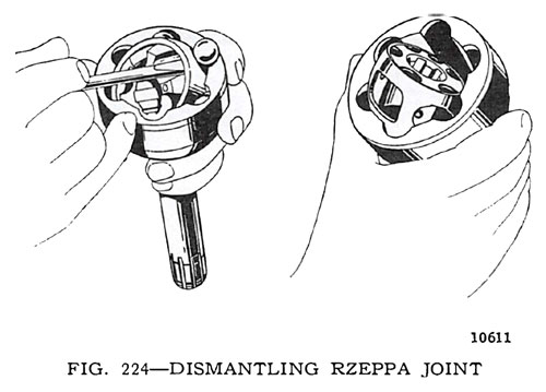
• Push down on various points of the inner race and cage until the balls can be removed with the help of a small screw driver in the manner illustrated in Fig. 224.
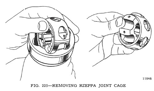
• There are two large elongated holes in the cage as well as four small holes. Turn the cage so the two bosses in the spindle shaft will drop onto the elongated holes and lift out the cage. See Fig. 225. f. To remove the inner race, turn it so one of the bosses will drop into an elongated hole in this cage and shift the race to one side and lift it out.
• Reassembly of the joint is the reverse of dismantling. Be careful not to damage parts and see that they are clean of all dirt and grit. (M-8, p 190)
Installation - Bendix Type Shaft
To install the Bendix type axle shaft and universal joint assembly in the housing proceed as outlined below.
• Clean all parts of dirt and foreign matter.
• Enter universal joint and axle shaft assembly in the housing, taking care not to knock out the inner oil seal. Enter the splined end of the axle shaft into the differential and push into place.
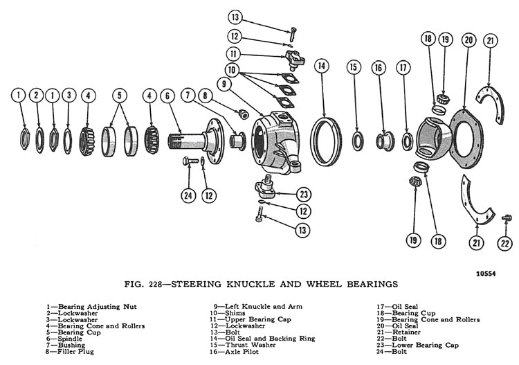
• Install wheel bearing spindle Fig. 228.
• Install the brake tube and brake backing plate.
• Grease and assemble wheel bearings and install the wheel hub and drum on the wheel bearing spindle. Install the wheel bearing washer and adjusting nut. Tighten nut until there is a slight drag when the hub is turned. Then back off approximately one-sixth turn. Install locking washer and nut, tighten nut, and then bend the lock washer over the lock nut.
• Install axle shaft washer, nut and cotter pin.
• Install the hub cap.
• Install the wheel.
• Check front wheel alignment as outlined in "Steering" Section.
• Bleed the brakes.
• Fill the universal joint housing with lubricant through the filler plug opening. (M-10, p192)
Installation - Rzeppa Type Joint
In Early Type Steering Knuckle. Installation of the Rzeppa-type axle shaft and universal joint in steering knuckles not equipped with spindle bushing Fig. 228, is the same as outlined above for the Bendix-type joint except the shimming procedure as covered in Par. M-9. When the Rzeppa joint is installed, disregard instructions for shim installation and install .060° [1,524 mm.] shims. (M-11, p192)
Steering Knuckle Pivot Pins (King Pin)
The steering knuckle pivot pins pivot on tapered roller bearings. Replacement of these bearings requires removal of the hub and brake drum assembly, wheel bearings, axle shaft, spindle, steering tie rod, and steering knuckle. Disassemble the steering knuckle as follows:
• Remove the eight screws shown in Fig. 228 which hold the oil seal retainer in place.
• Remove the four screws holding the lower pivot pin bearing cap.
• Remove the four screws holding the upper bearing cap in place. The steering knuckle can now be removed from the axle.
• Wash all parts in cleaning solvent. Replace any damaged or worn parts. Inspect the bearing and races for scores, cracks or chips. Should the bearing cups be damaged, they may be removed and installed with Special Driver W-138.
Note 2: On Model CJ-3A and later models .058" was added to the bottom face of the king pin boss on the steering knuckles. This eliminated the lower king pin bearing shims and the adjustment is made by shims at the top bearing cap only. (M-14, p193)
Assembly Install
Reverse the procedure of Par, M-14 to reassemble / assemble and install the unit. When reinstalling the steering knuckle, sufficient shims must be installed under the top bearing cap to obtain correct preload on the bearing. Shims are available in these thicknesses:
.003"
.005"
.010"
.030"
Install one each of the above shims at the top only. Install the bearing caps, lockwashers, and screws and tighten securely. Check the preload on the bearings by hooking a spring scale, Tool C-690, in the hole in the knuckle arm for the tie rod socket. Take the scale reading when the knuckle has just started its sweep. The kingpin bearing preload should be 12 to 16 lb. with the oil seal removed. Remove or add shims to obtain a preload within these limits. If all shims are removed and adequate preload is still not obtained, a washer may be used under the top bearing cap to increase preload. When a washer is used, shims may have to be reinstalled to obtain proper adjustment. (M-15, p193)
Looking for Front Axle parts for your vintage Willys or Jeep? Search Axle by Category or by Diagram
* Excerpt from the Service Manual for Universal Jeep Vehicles - pages 189-193
RELATED VIDEOS:
