Steering Service Standards - GPW
General
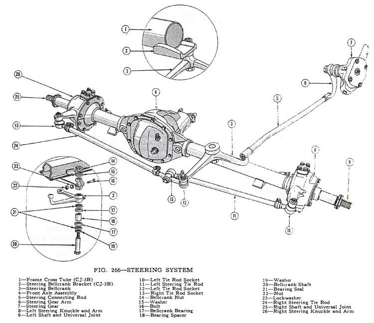
The stability and proper functioning of the steering system, Fig. 266, depends in a large measure upon correct alignment, and a definite procedure for inspection of the steering system is recommended. In so doing, nothing is overlooked and any trouble is ascertained in the shortest possible time. It is suggested that the following sequence be used:
• Equalize tire pressures and level vehicle.
• Inspect spindle pivot pins and wheel bearing looseness.
• Check wheel runout.
• Test wheel balance and bearing adjustment.
• Check for spring sag.
• Inspect brakes and shock absorbers.
• Check steering assembly and the steering connecting rod.
• Check caster.
• Check toe-in.
• Check toe-out on turns.
• Check camber.
• Check king pin inclination.
• Check turning angle
• Check tracking of front and rear wheels.
• Check frame alignment. (O-1, p214)
Adjustment
When adjusting a steering gear remove all loads from the unit by disconnecting the steering connecting rod (drag link) from the steering arm and also loosen the instrument panel bracket and the steering gear to frame bolts to allow the steering post to correctly align itself. When retightening the steering gear to frame bolts use a torque wrench pull of 45 to 55 lb-ft. (6,2 a 7,6 kg-m.] on the bolts and 30 to 40 lb-ft. (4,15 a 5,5 kg-m.] on the 11 bolts.
Note: If the steering-gear-to-frame bolts are not properly torqued, they will eventually loosen during operation of the vehicle. Loose bolts will result in elongated bolt holes making maintenance of bolt torque difficult, and may allow position of the steering columns to be misaligned. Therefore, proper torquing is extremely important. Do not tighten the steering gear to dampen out steering trouble. Adjust the steering only to remove lost motion or play within the unit. (O-2, p214)
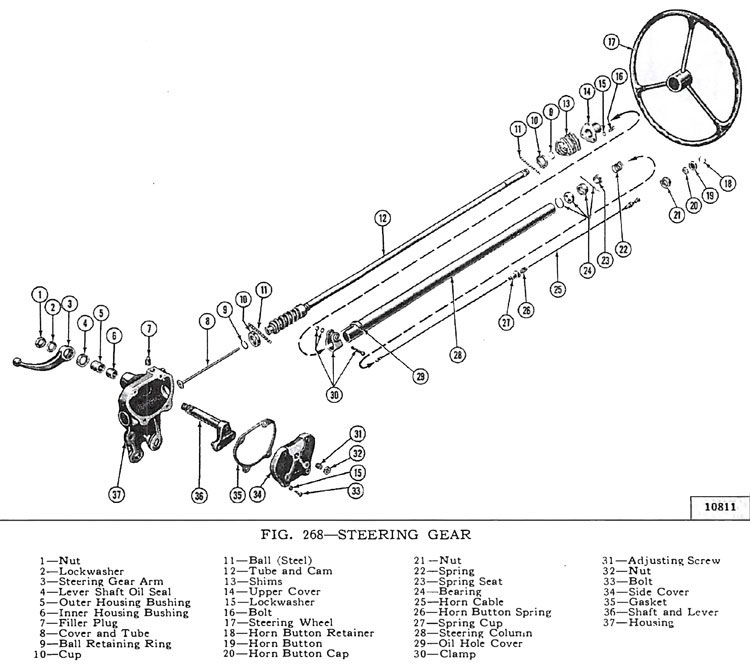
The cam and lever steering gear is illustrated in Fig. 268. It consists of a spiral cam, and a cross shaft and lever assembly with two lever studs. When the steering wheel is turned, the cam moves the studs, causing rotary movement of the cross shaft, which in turn causes angular movement of the steering arm. Two adjustments of the steering gear are necessary: up and down play of the steering shaft, and adjustment of the lever studs (tapered pins) in the cam groove. Adjustment of the ball thrust bearings to eliminate up and down play of the steering shaft is accomplished by removing shims which are installed between the steering gear housing and the upper cover. Before making this adjustment loosen the housing side cover adjusting screw to free the pins in the cam groove. Loosen the housing cover to cut and remove a shim or more as required. Install the screws and tighten. Adjustment should be made to have a slight drag but allow the steering wheel to turn freely with thumb and forefinger lightly gripping the rim. Shims installed for adjustment are .002 ", .003", and .010" [.0508, .0762 and .254 mm.] in thickness. Adjustment of the tapered pins in the cam groove is accomplished by adjusting screw. Unlock the adjusting screw and turn it in until a very slight drag is felt through the mid-position when turning the steering wheel slowly from one extreme position to the other. Backlash of the pins in the groove shows up as end play of lever shaft, also as backlash of steering arm. The cam groove is purposely cut shallow in the straight ahead driving position for each pin. This feature permits a close adjustment for normal straight ahead driving and provides precision steering and permits take up of backlash at this point after the wear occurs without causing a bind elsewhere. Always adjust within the high range through the mid-position of pin travel. Do not adjust off "straight ahead" position. Backlash in turned positions is not objectionable. (O-3, p215)
Steering Connecting Rod
To adjust the ball joint at the steering gear arm, screw in the end plug firmly against the ball, then back off one full turn and lock with a new cotter pin inserted through holes in the tube and the slot in the adjusting plug. The above adjustments will give the proper spring tension and avoid any tightness when swinging the wheel from maximum left to right tum. The ball joints must be tight enough to prevent end play and yet loose enough to allow free movement. (O-7, p 217)
Front Wheel Alignment
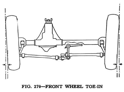
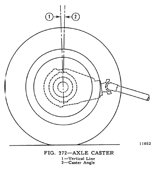
The most important factors of front wheel alignment are wheel camber, axle caster and wheel toe-in. Wheel toe-in is the distance the wheels are closer together at the front than at the rear. Wheel camber is the amount the wheels incline outward at the top from a vertical position. Front axle caster is the amount in degrees that the steering pivot pins are tilted towards the front or rear of the vehicle. Positive caster is inclination of the top of the pivot pin towards the rear of the vehicle. Zero caster is the vertical position of the pivot pin. Negative or reverse caster is the inclination of the top of the pin towards the front of the vehicle. (O-9, p 217)
Front Wheel Toe-In
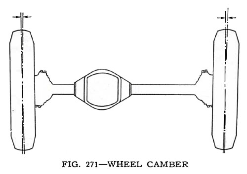
Toe-in as illustrated in Fig. 270, is necessary to offset the effect of camber as shown in Fig. 271. In the absence of a wheel aligning fixture, toe-in may be set by measuring between the front wheels at the edge of the rim, at the flange or at the tire tread center. When making this adjustment the wheels must be in a straight ahead position. It is highly important that toe-in be checked regularly and if found to be out of adjustment, correction should be made immediately. The correct toe-in of these models is found in the specifications of this section. (O-10, p 218)
Toe-In Adjustment
The toe-in may be adjusted with a line or straight edge as the vehicle tread is the same in front and rear. To set the adjustment both tie rods must be adjusted as outlined below: Set the tie rod end of the steering bell-crank at right angles with the front axle. Place a straight edge or line against the left rear wheel and left front wheel to determine if the wheel is in a straight ahead position. If the front wheel tire does not touch the straight edge at both the front and rear, it will be necessary to adjust the left tie rod by loosening the clamps on each end and turning the rod until the tire touches the straight edge. Check the right hand side in the same manner, adjusting the tie rod if necessary, making sure that the bell-crank remains at right angles to the axle. When it is determined that the front wheels are in the straight ahead position, set the toe-in by shortening each tie rod approximately one-half turn. (O-11, p218)
Front Wheel Camber
The purpose of camber Fig. 271, is to more nearly place the weight of the vehicle over the tire contact on the road to facilitate ease of steering. The result of excessive camber is irregular wear of tires on outside shoulders and is usually caused by bent axle parts. The result of negative or reverse camber, if excessive, will be hard steering and possibly a wandering condition. Tires will also wear on inside shoulders. Negative camber is usually caused by excessive wear or looseness of front wheel bearings, axle parts or the result of a sagging axle. Unequal camber may cause any or a combination of the following conditions: unstable steering, wandering, kick-back or road shock, shimmy or excessive tire wear. The cause of unequal camber is usually a bent steering knuckle or axle end. Correct wheel camber is set in the axle at the time of manufacture and cannot be altered by any adjustment. It is important that the camber be the same on both front wheels. Heating of any of these parts to facilitate straightening usually destroys the heat treatment given them at the factory. Cold bending may cause a fracture of the steel and is also unsafe. Replacement with new parts is recommended rather than any straightening of damaged parts. (O-12, p218)
Axle Caster
Caster angle is established in the axle design by tilting the top of the kingpin toward the rear and the bottom of the kingpin forward so that an imaginary line through the center of the kingpin would strike the ground at a point ahead of the point of tire contact. The purpose of caster Fig. 272, is to provide steering stability which will keep the front wheels in the straight ahead position and also assist in straightening up the wheels when coming out of a turn. Caster of the front wheels is preset. If the angle of caster, when accurately measured, is found to be incorrect, correct it to the specification given at the end of this section by either installing new parts or installing caster shims between the axle pad and the springs. (O-13, p 218)
4Wheel Drive-Turning Angle
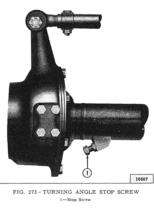
To avoid possible damage to the universal joints on the front axles of 4-wheel drive vehicles, it is advisable to check the turning angle. Wearing away of the upset edge on the spindle housing bolt which contacts the stop screw will increase the turning angle to the point where the universal joints may be damaged. The stop screw for setting the turning angle is shown in Fig. 273. To adjust the screw, it is necessary to break the weld holding the screw in position. When the adjustment has been made, reweld the screw in place to prevent any movement. (O-14A, p 219)
Front Wheel Shimmy
Wheel shimmy may be caused by various conditions in the wheels, axle or steering system, or a combination of these conditions. Outlined below will be found the usual corrections of this fault:
• Equalize tire pressures and see that they are according to specifications.
• Check the wheel bearings for looseness. Be sure that the inner wheel bearing race is not too loose on the spindle.
• Remove both steering knuckles and carefully inspect the upper and lower king pin bearings. Inspect the bearing cups for evidence of brinelling, pitting, or fretting. Any bearings that show the slightest imperfection must be replaced. Reassemble and lubricate the front axle and steering linkage, installing new steering knuckle oil seals if present seals show any wear.
• Check wheel run-out. This check should include radial run-out and wheel looseness on the hub.
• Test wheel balance-check for blowout patches, uniform tire tread, vulcanized tires, mud on inside of wheels, and tires creeping on the rims.
• Try switching front wheels and tires to the rear, criss-crossing them in this operation.
• Check for front spring sag. Also check for broken spring leaves, broken center spring bolt, loose spring clips (or tight clips), over-lubrication of spring leaves, spring shackle bracket loose on frame, and loose rear spring shackle. Be sure that the shock absorbers are operating properly to eliminate bobbing of the front end.
• Check brakes to make sure that one does not drag.
• Check the steering assembly and steering connecting rod. This includes the up-and-down-play of the steering worm shaft, end play of the cross shaft, tightness of the steering gear in the frame, tightness of steering gear arm, adjustment of the steering connecting rod and condition of the steering tie rod ball joint ends. Adjust the steering connecting rod (drag link) to maximum safe tightness at both ends. Examine the steering bellcrank bearings, the shaft in the mounting bracket, and the mounting bracket on the frame cross member.
• Check front axle caster. This should be the same on both sides, otherwise a locking brake may be indicated causing a twisting action of the axle. Correct caster is shown in specifications at the end of this section.
• Check the front wheel toe-in. See Specifications.
• Check wheel toe-out on turns. This gives you an indication of the proper angularity of the steering knuckle arms and tells whether or not they have been bent and require replacing. These may be checked by comparing them with new parts. If an arm is bent, check for a bent tie rod.
• Check wheel camber. This should be the same on both wheels as shown on the Specifications.
• Check the king pin inclination. See Specifications.
• Check the tracking of the front axle and frame alignment, which may be incorrect due to an accident. (O-17, p220 - 221)
Looking for Steering parts for your vintage Willys or Jeep? Search Steering by Category or by Diagram
* Excerpt from the Service Manual for 41-45 MB, GPW
